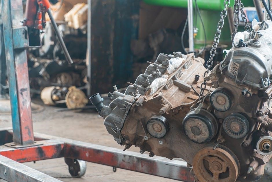
Valve guide replacement is a crucial engine repair‚ often needed after valve damage or during a comprehensive rebuild.
Properly aligned guides ensure optimal valve operation and longevity‚ preventing issues like oil leaks and reduced performance.
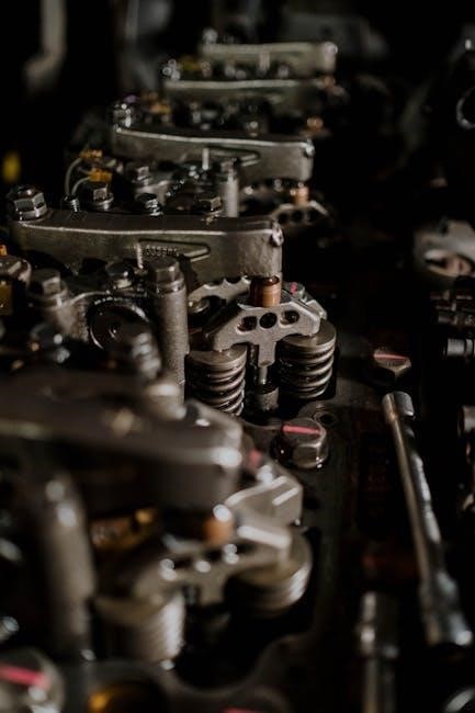
What are Valve Guides?
Valve guides are precision-machined sleeves inserted into the cylinder head‚ providing a low-friction surface for the valve stems to move within.
They maintain correct valve alignment during operation‚ ensuring the valve seals properly against the valve seat.
These guides are typically made from cast iron‚ bronze‚ or steel‚ chosen for their wear resistance and ability to withstand high temperatures.
Cracked or worn guides compromise sealing‚ leading to oil consumption and reduced engine efficiency.
Why Replace Valve Guides?
Valve guide replacement becomes necessary when wear or damage compromises their ability to maintain precise valve control.
Bent valves‚ often resulting from engine issues‚ can crack guides‚ necessitating their change.
Excessive valve stem play‚ indicated by noticeable movement‚ signals guide wear.
Replacing guides restores proper valve alignment‚ preventing oil leaks‚ improving combustion efficiency‚ and ultimately‚ preserving engine performance and longevity. Ignoring worn guides leads to further damage.
Tools and Materials Needed
Successful valve guide work requires specialized tools like air hammers‚ valve guide drivers‚ and taps. Essential supplies include new guides‚ valves‚ springs‚ and cleaning solvents.
Specialized Tools
For effective valve guide replacement‚ several specialized tools are indispensable. An air hammer is frequently used for guide removal‚ particularly in cast iron heads‚ offering controlled force. A fine-thread tap‚ of appropriate size‚ is crucial for the tapping and bolting removal method‚ creating a secure point for extraction.
Valve guide drivers are essential for pressing in new guides‚ ensuring proper alignment and preventing damage. Precision measuring tools‚ like micrometers‚ are needed for verifying guide sizing. Finally‚ a valve seat grinder becomes necessary if seat regrinding is required post-installation‚ ensuring a perfect seal.
Essential Supplies
Beyond specialized tools‚ a range of essential supplies are needed for a successful valve guide replacement. New valve guides (or inserts) are‚ of course‚ paramount‚ ensuring correct sizing and material compatibility. High-quality sealant is vital for preventing oil leaks around the new guides.
Cleaning solvents are necessary for thoroughly cleaning the cylinder head before and after guide work. Lubricating oil aids in the pressing-in process‚ minimizing friction and preventing damage. Finally‚ protective gear – gloves and eye protection – are crucial for safety throughout the procedure.
Preparation Before Removal
Prior to valve guide removal‚ meticulously disassemble the valves‚ springs‚ and retainers. Thoroughly clean the cylinder head to prevent debris from interfering with the process.
Valve Disassembly
Begin the process by carefully removing all valves‚ ensuring you keep track of their original positions for correct reinstallation. Next‚ detach the valve springs and retainers‚ paying attention to the orientation of the components. Lock shims or keepers must also be removed.
Documenting the disassembly process with photos or notes is highly recommended. This prevents confusion during reassembly. A valve spring compressor is essential for safely removing the valve springs. Remember to handle all parts with care to avoid damage‚ as bent valves often necessitate guide replacement.
Cleaning the Cylinder Head
Thoroughly cleaning the cylinder head is paramount before commencing valve guide work. Remove all carbon buildup‚ oil residue‚ and debris from the valve guide bores and surrounding areas. A parts cleaning solvent and brushes are effective for this task.
Ensure no abrasive particles remain‚ as they can compromise the precision fit of the new guides. Inspect the head for any cracks or damage. A clean workspace is crucial to prevent contamination during installation. This meticulous preparation ensures accurate measurements and a successful outcome.
Valve Guide Removal Techniques
Various methods exist for removing valve guides‚ including using an air hammer‚ tapping with a bolt‚ drifting (for cast iron)‚ and specialized pullers.
Choosing the right technique depends on the head material and guide’s condition.
Using an Air Hammer
Employing an air hammer is a common technique for valve guide removal‚ particularly when dealing with stubborn or corroded guides.
It’s crucial to use a punch with a rounded tip to avoid damaging the cylinder head.
Apply short‚ controlled bursts‚ working around the guide’s circumference to gradually loosen it.
Caution is paramount; excessive force can easily harm the head.
Support the head adequately during this process.
Some technicians recommend slightly collapsing the guide inward before attempting to drive it out‚ easing the removal process.
Always wear appropriate safety glasses!
Tapping and Bolting Method
The tapping and bolting method offers a controlled approach to valve guide removal. This involves tapping fine threads into the side of the old guide‚ creating an anchor point.
A bolt is then screwed into these threads‚ allowing you to pull the guide out using a steady‚ even force.
This technique minimizes the risk of damaging the cylinder head compared to more forceful methods. Ensure the bolt is securely engaged and apply consistent pressure.
It’s a preferred method for those seeking a less aggressive removal strategy.
Drifting Method (for Cast Iron Heads)
The drifting method‚ traditionally used for cast iron cylinder heads‚ involves carefully hammering the old valve guides out from the underside of the head.
A properly sized drift – a steel rod slightly smaller than the guide’s outer diameter – is essential to avoid damaging the head’s material.
Gentle‚ consistent tapping is key; avoid forceful blows. New guides are then drifted into place‚ ensuring a snug fit. This method requires precision and a thorough understanding of the head’s construction.
Valve Guide Installation
Installing new valve guides requires precision‚ often utilizing a press or specialized drivers to ensure a secure and properly aligned fit within the cylinder head.
Pressing in New Guides
Pressing in new valve guides demands careful technique to avoid damaging the cylinder head. Ensure the guides are thoroughly cleaned and lightly lubricated with assembly lube before installation.
Utilize a suitable press with appropriate adapters to apply even pressure‚ avoiding angled insertion.
Slow‚ controlled pressure is key; monitor the guide’s descent to confirm proper alignment.
Frequently check for squareness during the process‚ and avoid excessive force‚ which could distort the head.
Proper depth is critical for optimal valve function.
Using Valve Guide Drivers
Valve guide drivers offer a controlled method for installing new guides‚ especially beneficial for DIY mechanics. Select a driver set matching your guide’s outer diameter and head’s specifications.
Lubricate the guide and driver before use.
Employ a hammer to gently drive the guide into place‚ ensuring consistent‚ straight alignment.
Avoid forceful hammering‚ which can damage the head or guide.
Regularly check for squareness throughout the installation process‚ guaranteeing proper valve geometry.
Valve Guide Inserts
Valve guide inserts provide a robust repair option‚ particularly when original guides are severely worn. They involve drilling out the existing guide and pressing in a new‚ hardened insert.
Drilling Out Existing Guides
Drilling out existing valve guides is a key step when installing inserts. This process requires precision to avoid damaging the cylinder head itself. Typically‚ a portion of the original guide’s inner diameter is carefully removed using specialized drill bits.
It’s vital to maintain perfect alignment during drilling to ensure the insert will seat correctly. King Motorsports Unlimited emphasizes this step to eliminate misalignment issues and maintain perfect valve seat alignment. Properly sized drill bits and a stable setup are essential for a successful outcome.
Pressing in Inserts
Pressing in new valve guide inserts follows the drilling process‚ demanding accuracy and controlled force. The inserts‚ typically made of a durable bronze alloy‚ are carefully aligned with the prepared guide bore. A specialized press or tool is used to seat the insert fully and squarely within the cylinder head.
Consistent pressure is crucial to avoid damaging the head or distorting the insert. King Motorsports Unlimited highlights this method for maintaining perfect alignment‚ ensuring optimal valve operation and longevity.
Checking Valve Guide Alignment
Precise valve guide alignment is paramount for optimal engine performance and preventing valve seat issues. Misalignment leads to premature wear and potential oil leaks.
Importance of Alignment
Maintaining perfect valve guide alignment is absolutely critical for several reasons. A misaligned guide directly impacts valve seat contact‚ potentially leading to incomplete sealing and compression loss. This results in reduced engine power and efficiency.
Furthermore‚ improper alignment accelerates valve and valve seat wear‚ necessitating more frequent repairs. It can also cause oil to seep past the valve stem seals‚ contributing to oil consumption and potential engine damage. Ensuring guides are perfectly perpendicular to the valve seat is essential for longevity.
Methods for Checking Alignment
Checking valve guide alignment requires precision. A common method involves using a dial indicator to measure runout along the guide’s inner diameter. Any deviation indicates misalignment. Another technique utilizes a precision square to verify the guide’s perpendicularity to the cylinder head surface.
Experienced machinists often employ specialized alignment tools for accurate assessment. Visual inspection alone isn’t sufficient; precise measurement is key. Addressing even minor misalignment is crucial for optimal valve operation and preventing future issues.
Valve Seat Grinding
Valve seat grinding is often necessary after guide replacement to ensure a proper valve seal and perpendicularity.
This process restores the seat’s geometry for optimal contact with the valve.
Necessity of Grinding
Grinding valve seats after replacing guides is frequently recommended‚ particularly when addressing issues like bent valves or significant wear. The machine shop experts emphasize that new guides don’t automatically guarantee perfect alignment with the existing seats.
Maintaining perpendicularity between the valve and seat is paramount for a complete seal‚ preventing compression loss and ensuring efficient combustion. Without grinding‚ imperfections can lead to premature wear‚ reduced engine power‚ and potential valve damage. Therefore‚ a valve seat grind is a preventative measure for long-term engine health.
Grinding Procedures
Valve seat grinding typically involves using specialized tools to resurface the valve seat to a precise angle. This process ensures a perfect mating surface with the valve. A swirl-pattern grinding is often employed to create a consistent seal.
The technician carefully assesses the seat’s condition before grinding‚ addressing any pitting or damage. Following the grinding‚ a lapping compound is used to further refine the seal. Proper technique and precision are vital for optimal results‚ guaranteeing a leak-free and efficient valve train.

Determining if Valve Guide Replacement is Needed
Worn valve guides manifest as excessive valve stem play‚ oil consumption‚ and potential valve seal failure. Inspection reveals looseness‚ impacting performance and requiring replacement.
Signs of Worn Valve Guides
Identifying worn valve guides is critical for maintaining engine health. Excessive oil consumption is a primary indicator‚ as worn guides allow oil to seep past the valve seals and into the combustion chamber. Valve stem play‚ noticeable when wiggling the valve stem‚ signifies guide looseness.
Furthermore‚ blue smoke from the exhaust‚ especially during deceleration‚ often points to oil burning due to leaky valve seals caused by guide wear. A ticking or clicking sound from the valve train can also suggest valve stem movement within worn guides. Regular inspections during engine maintenance can help detect these signs early.
Valve Stem Play
Valve stem play directly indicates the condition of the valve guides. Excessive play signifies wear within the guide bore‚ allowing the valve stem to move laterally. This movement compromises valve alignment and seal integrity‚ leading to oil leakage and reduced engine efficiency.
To check for play‚ grasp the valve stem and attempt to wiggle it perpendicular to the valve’s axis. Any noticeable movement confirms worn guides. Addressing this play through guide replacement is crucial for restoring proper valve control and preventing further engine damage.
Working with Aluminum Cylinder Heads
Aluminum heads require careful handling during guide replacement due to their softer material. Drilling and pressing operations demand precision to avoid damaging the head’s structure.
Specific Considerations
Working with aluminum cylinder heads presents unique challenges compared to cast iron. The material’s softer nature necessitates a more delicate approach during valve guide removal and installation.
Precise temperature control is vital; excessive heat can easily warp or damage the aluminum.
Using specialized tools designed for aluminum is highly recommended‚ minimizing the risk of cracking or thread damage.
Furthermore‚ aluminum expands and contracts differently than cast iron‚ impacting interference fit tolerances.
Potential Challenges
Aluminum head repairs can encounter difficulties like seized valve guides‚ requiring careful extraction to avoid head damage.
Cracked guides‚ stemming from bent valves‚ demand meticulous removal to prevent further complications.
Maintaining precise alignment during installation is critical‚ as misalignment leads to valve sealing issues.
The risk of damaging the softer aluminum material is always present‚ necessitating slow‚ controlled procedures and appropriate tooling.
Properly sizing inserts is also crucial for a secure fit.
Working with Cast Iron Cylinder Heads
Cast iron heads allow for drifting guides out and in‚ a simpler removal method compared to aluminum.
However‚ material considerations are vital to avoid cracking during the process.
Differences in Removal
Removing valve guides from cast iron cylinder heads traditionally involves a drift and hammer technique. This method utilizes a precisely sized drift‚ carefully hammered to push the old guides out. Unlike aluminum heads‚ which are more prone to damage‚ cast iron’s robustness allows for this direct approach.
However‚ caution is still paramount; excessive force can still crack the head. A machinist friend suggests tapping threads into the old guide and using a bolt for extraction‚ offering a controlled removal. This contrasts sharply with aluminum head removal‚ often requiring specialized tools to avoid damage.
Material Considerations
Cast iron heads demand guides compatible with their material properties. Bronze valve guides are a common choice‚ offering excellent wear resistance and compatibility with cast iron. However‚ inserts are frequently used‚ requiring drilling out the original guide’s inner diameter before pressing in a new‚ hardened insert.
This approach maintains perfect alignment and addresses wear issues. Selecting the correct material is vital; mismatched materials can lead to accelerated wear or even seizing. Careful consideration of the engine’s application and operating conditions is essential for optimal longevity.
Post-Installation Checks
Post-installation‚ verify smooth valve operation and check for binding.
Perform a leak test to confirm proper sealing‚ ensuring the valve guides effectively prevent oil and compression loss.
Valve Operation
After reassembly‚ meticulously check each valve’s movement throughout its entire range. Valves should move freely without any noticeable binding or resistance. Ensure the valve spring correctly seats the retainers and locks‚ preventing premature failure.
Observe the valve stem’s alignment within the new guide; any wobble indicates potential issues. A properly installed guide will provide a snug‚ yet smooth‚ fit. Confirm the valve fully closes and seals against the valve seat when returned to the closed position‚ preventing combustion gas leakage.
Leak Testing
Post-installation‚ rigorous leak testing is paramount to verify the success of the valve guide replacement. Introduce compressed air through the intake or exhaust port with the valves closed.
Submerge the cylinder head in liquid (like kerosene) and observe for bubbles‚ indicating leaks around the valve seats or guides. Any detected leaks necessitate further investigation and potential re-grinding of the valve seats. A successful test confirms a proper seal and prevents combustion gas escape‚ ensuring optimal engine performance.
Common Mistakes to Avoid
Avoid damaging the cylinder head during guide removal or installation‚ and ensure correct guide depth and alignment; Improper installation leads to valve issues.
Damaging the Cylinder Head
Cylinder head damage is a significant concern during valve guide work. Aggressive removal techniques‚ like excessive force with an air hammer or drift‚ can crack or distort the head.
Incorrectly sized tools or improper pressing methods can also cause issues.
Be especially careful with aluminum heads‚ as they are more susceptible to damage than cast iron.
Always support the head adequately during the process and avoid applying uneven pressure.
Protect valve seats during guide removal to prevent unnecessary wear or damage.
Incorrect Guide Installation
Improper guide installation leads to premature failure and engine problems. Guides must be pressed in straight and to the correct depth; misalignment causes valve binding and wear.
Using the wrong size driver or applying uneven pressure during installation can distort the guide or damage the cylinder head.
Ensure the guide is fully seated and doesn’t protrude.
Always verify guide alignment after installation‚ as even slight errors impact valve geometry and sealing‚ leading to oil leaks and reduced performance.
Finding the Right Valve Guides
Selecting correct valve guides requires knowing precise sizing and material specifications for your engine.
Options include cast iron‚ bronze‚ and steel‚ each offering unique durability and performance characteristics.
Sizing and Specifications
Accurate valve guide sizing is paramount for proper valve stem-to-guide clearance. This clearance impacts oil control and valve stability. Guides aren’t universally sized; specifications vary significantly based on engine make‚ model‚ and even valve position (intake vs. exhaust).
Consult your engine’s service manual for the correct inner diameter of the guide and the corresponding valve stem diameter. Measurements should be precise‚ often down to the thousandth of an inch. Incorrect sizing can lead to valve sticking‚ excessive wear‚ or oil consumption. Always verify compatibility before installation.
Material Choices
Valve guides are commonly manufactured from several materials‚ each with distinct advantages. Cast iron guides are traditional‚ durable‚ and cost-effective‚ suitable for many cast iron cylinder heads. However‚ they can wear over time. Bronze guides offer superior wear resistance and are often preferred for performance applications.
Aluminum cylinder heads typically require specialized guides made from materials like silicon bronze or ductile iron to manage thermal expansion differences. Valve guide inserts‚ often steel‚ provide a hardened‚ replaceable wear surface‚ extending guide life and simplifying future repairs.
Professional Machining Services
Seeking professional help ensures precise valve guide alignment and seat grinding. Experienced machinists possess specialized tools and expertise for optimal results‚ preventing costly errors.
When to Seek Professional Help
Determining when to consult a machinist is vital for a successful valve guide replacement. If you lack specialized tools like valve guide drivers or air hammers‚ professional assistance is recommended.
Furthermore‚ if you’re uncomfortable drilling or pressing components‚ or if the cylinder head material is unknown‚ a machinist’s expertise is invaluable.
Specifically‚ aluminum heads require precise techniques to avoid damage.
Don’t hesitate to seek help if you suspect significant cylinder head distortion or if achieving proper valve seat perpendicularity proves challenging.
Benefits of Professional Services
Professional machining offers precision and expertise unattainable with DIY methods. A machinist ensures accurate valve guide alignment‚ critical for optimal engine performance and longevity. They possess specialized tools for precise drilling‚ pressing‚ and valve seat grinding.
Furthermore‚ they can identify and correct cylinder head distortions‚ preventing future issues.
Utilizing professional services minimizes the risk of damaging the head and guarantees a quality repair‚ ultimately saving time and potential costly mistakes.
Resources and Further Information
Online forums‚ like Miata Turbo Forum and Jag-lovers‚ provide valuable insights and shared experiences. Technical manuals offer detailed procedures for specific engine types‚ aiding successful valve guide replacement.
Online Forums
Online forums are invaluable resources for those tackling valve guide replacement. Platforms like Miata Turbo Forum and The MG Experience host discussions with experienced enthusiasts and mechanics. These communities offer practical advice‚ troubleshooting tips‚ and shared experiences related to specific engine types – such as the 4G63 or MGB.
You can find detailed threads on techniques like using air hammers‚ tapping methods‚ and drift installations. Furthermore‚ forums like XK – Jag-lovers provide insights into potential issues‚ such as the necessity of valve seat grinding post-replacement‚ and help determine if replacement is even needed.
Technical Manuals
Technical manuals provide detailed‚ step-by-step instructions for valve guide replacement‚ specific to your engine model. These resources often outline torque specifications‚ proper tool usage‚ and critical alignment procedures. While online forums offer practical advice‚ manuals provide a foundational understanding of the process.
However‚ remember that some manuals‚ like those referenced in forum discussions regarding MGBs‚ may not explicitly mention every related step – such as valve seat grinding. Supplementing manual instructions with forum insights ensures a comprehensive approach to this intricate repair.